OBD II TERMINOLOGY
Warm-up Cycle
After each startup, a warm-up cycle is accomplished when the engine coolant temperature (ECT) rises a minimum of 40°F (22° C) and reaches a minimum of 160°F (71° C). When 40 Warm-up cycles have been achieved, the ECM will clear all history diagnostic trouble codes (DTC) and freeze frame data (FFD). It does not reset readiness flags or clear permanent diagnostic trouble codes (PDTC). It is not required to run monitor tests.
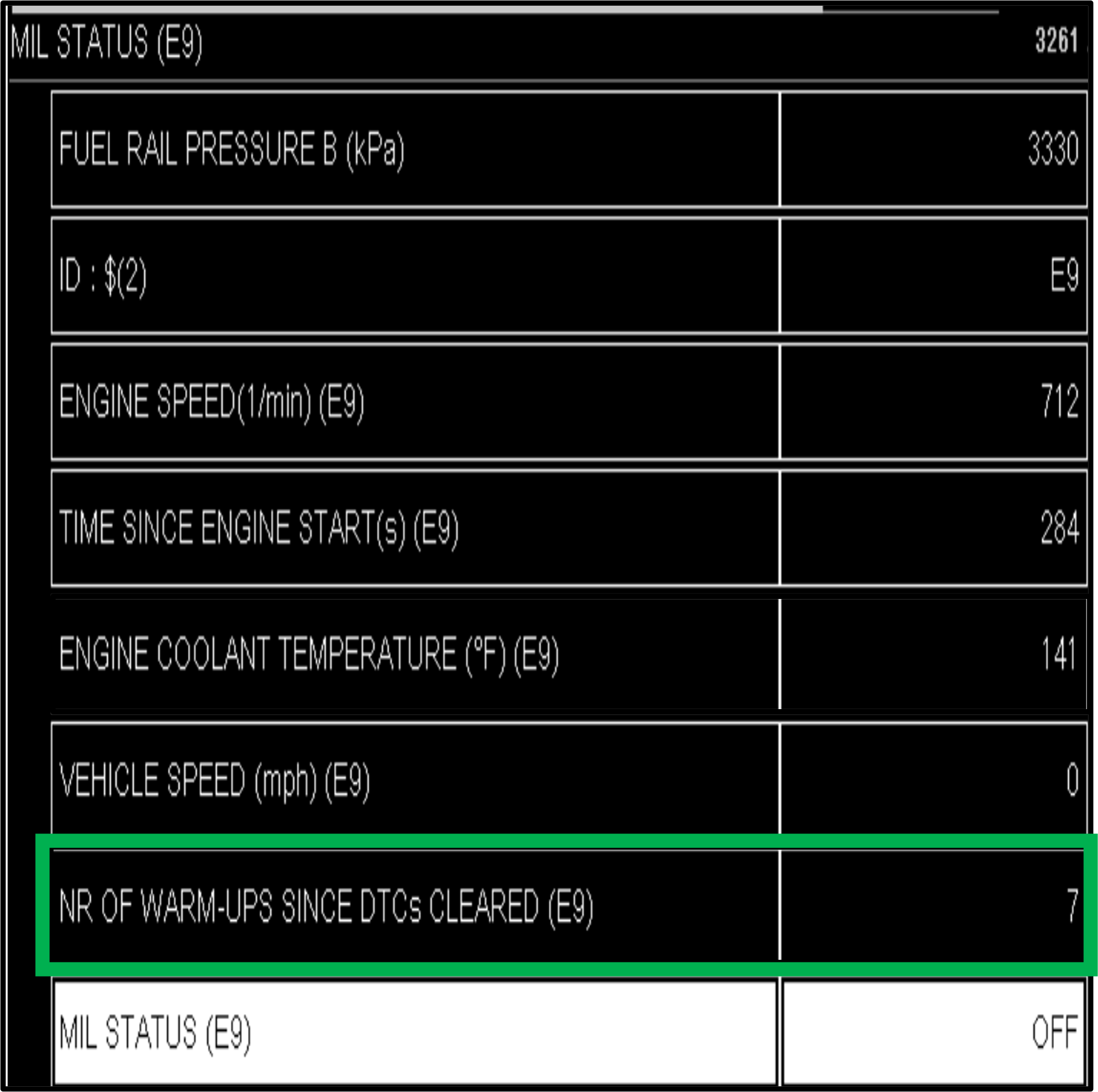
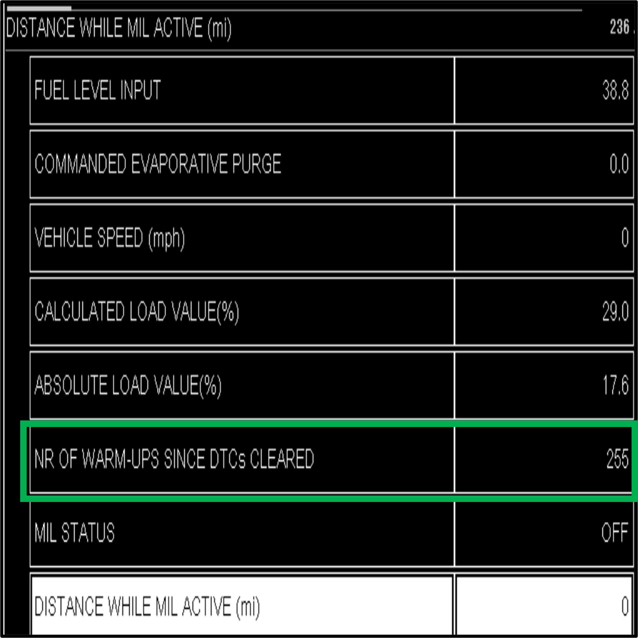
In the example shown below, the warm-up cycle counter is 7. For the average vehicle, this means the memory was cleared recently. The counter will stop at 255, which means it has been a long time since the memory was reset.
Cold Soak
For a cold start, the engine coolant temperature (ECT) and intake air temperature (IAT) sensors must be within approximately 10°F of each other and below 122°F (50° C) at startup. Cold start conditions are sometimes required to run the monitor tests for the air-fuel ratio sensor heater(s) (AFRS) and oxygen sensor heater(s) (HO2S), secondary air injection (AIR), and evaporative emission system (EVAP).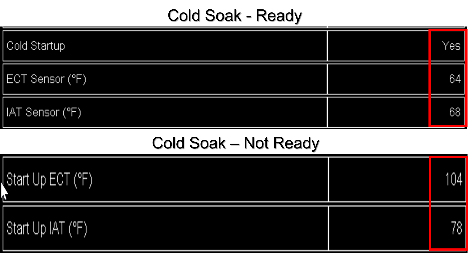
Enable Criteria
Enable Criteria, also called Enable Conditions, are engine and driving conditions for a monitor test. Each diagnostic trouble code (DTC) has its enabling conditions. When the enable criteria are met, the ECM will run the specific monitor test(s). If the enable criteria are not met, the test will not run. A failed monitor test result will set a pending or confirmed DTC.
Note the Secondary Parameters shown below. For this P0135 DTC, there can be no active DTCs for the test to run. Secondary parameters include the enabling conditions. P0135 is a Type B DTC. The monitor test must be on two consecutive trips to illuminate the MIL.
Trip
A trip requires a key-on engine-off (KOEO) or key-on engine running (KOER) condition, completing the enable criteria for the monitor test, and then a key-off event. The trip ends once the scan tool no longer communicates with the ECM. 
When the malfunction indicator lamp (MIL) is on, the ECM/PCM will deactivate the MIL after three consecutive trips where the same fault is not detected. For instance, a vehicle with a Diagnostic Trouble Code (DTC) P0420 will have the MIL turned off if, during three successive trips, the technician drives the vehicle and meets the enabling criteria for a P0420 and the ECM/PCM does not detect a fault. The DTC will be stored as a historical code.
Combing the Enabling Criteria and a Trip
The following video shows the enabling criteria combined with a trip. During the test drive, the enabling criteria for the Catalyst monitor test are met and interrupted multiple times. Due to changes in driving conditions, the monitor test is temporarily suspended. Finally, the test is "Done This Trip."
The top of the scan tool screen shows the enabling criteria for this test. Once the min/max arrows disappear, indicating that the enable criteria are being met and testing is "In Progress." Once the enabling conditions are met for the required time, the monitor test shows "Done This Trip."
This is not a drive cycle because it focuses on only one readiness flag and related monitor test. This data was recorded while using a Chrysler DRBIII scan tool.
Drive Cycle
A drive cycle consists of the Enable Criteria and a Trip. To complete an entire drive cycle, the enable criteria must be met in one key cycle, during which all readiness flags have been flipped to Complete. The drive cycle is complete, the trip ends when the key is turned off, and the scan tool no longer communicates with the vehicle.
It is unrealistic for the vehicle driver or technician working on the vehicle to complete all readiness flags in one drive cycle. Completing a drive cycle involves many variables, such as traffic, the type of roads, and the distance from a freeway. Most drive cycles require some part-throttle and steady driving at highway speed.
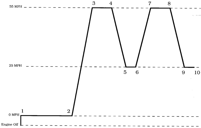
For more information on drive cycles, refer to the section on OBDII Drive Cycle.
Readiness Flag
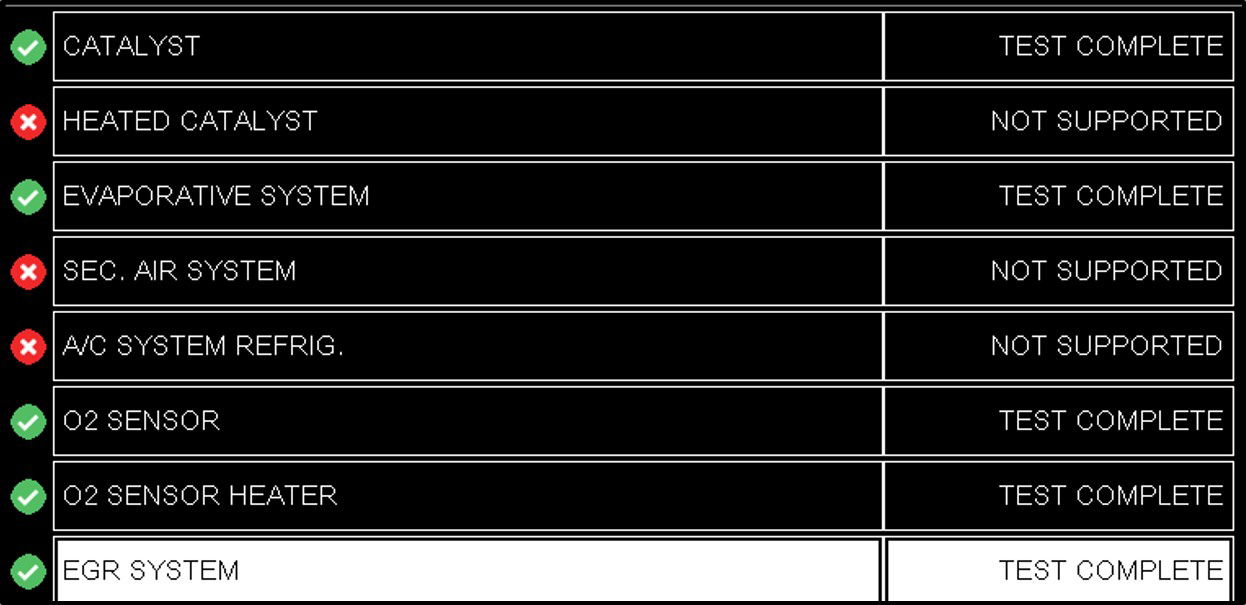
A readiness flag reports that a specific emission-related system has completed testing. Each readiness flag can consist of one or multiple individual monitor tests. State emissions programs use some readiness flags as part of an official Inspection, and a minimum number of readiness flags must be Completed to pass an emissions Inspection.
Readiness Flag Status
The readiness flag status indicates the ECM/PCM has completed testing of specific monitored emission systems. It does not indicate if the system passed or failed. If the monitor test required to flip the readiness flag to complete has not finished testing, the status on the scan tool will display Not Complete. If the monitor test needed to flip the readiness flag has completed testing, the readiness flag status will display Complete. A readiness flag showing Complete means the ECM/PCM has finished testing the system at least once since the memory was last reset.
Incomplete, Not Done, Not Ready
Since the last MODE $04 Diagnostic Clear was performed, one or more required readiness flag monitor tests have not run or failed (Pre-CAN). Before introducing the Controller Area Network (CAN) in 2008, the PCM did not have to switch to Complete, Done, or Ready if a readiness flag monitor test failed.
Complete, Done, Ready
Since the last MODE $04 Diagnostic Clear was performed, all Complete readiness flag monitor tests have completed testing at least one time. With the introduction of CAN, the readiness flag status must switch to Complete, Done, or Ready once testing is complete, whether the monitor tests pass or fail.
Non-Readiness Mode
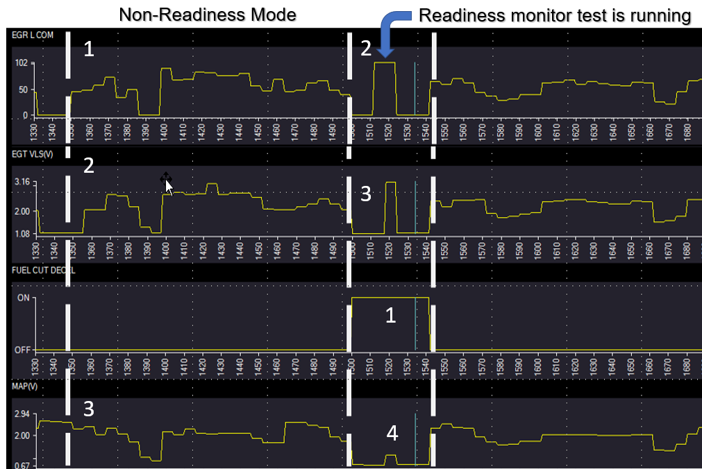
It occurs during normal operations when the enable criteria required to run a monitor test to set a readiness flag for completion are not met. The picture below shows the EGR system is working as designed. The EGR Command (1) represents the "ON" command to the solenoid. It also means that the general operating criteria like ECT, IAT, TPS, Load, etc. have been met. The movement of the EGR diaphragm (2) shows that the vacuum passed through the solenoid to the valve. The MAP Sensor (3) shows an intake manifold pressure change when the valve opens. The difference in the non-readiness mode is the system is not being tested for flow.
Readiness Mode
The readiness mode occurs during regular operation when the enable criteria required to run a monitor test(s) to set a readiness flag to complete are met. Fuel Cut Decel (1) shows the difference between the two modes. This additional criterion is required to run the monitor test that checks the EGR performance for flow. During a deceleration (1), the EGR solenoid is commanded "ON" (2), the EGR position sensor moves because of the intake manifold vacuum (3), and the MAP sensor (4) reports the changes to the ECM. When the ECM completes system testing, the readiness flag will be flipped to Complete. If a DTC is present, the system fails. If no DTC is set, the system passes.
Monitor Test
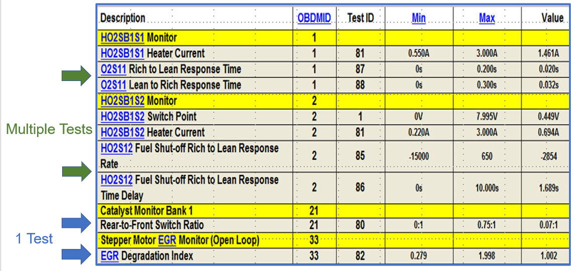
A monitor test is a system-specific test that sets a Diagnostic Trouble Code (DTC). A readiness flag requires one or more monitor tests to complete the testing of a component or system. If the required monitor test runs and passes, that readiness flag will flip to Complete. The readiness flag will be flipped to Complete when the ECM completes system testing. If a DTC is present, the system fails. If no DTC is set, the system passes.
Continuous Monitor Tests
The ECM monitors misfires, fuel systems, and comprehensive components while their individual enable criteria are met. A Continuous monitor test can run multiple times per trip to pass and fail during the same trip. The readiness flags status for misfire, fuel system, and comprehensive components are not used during a state emissions inspection for gasoline vehicles. In some cases, they are used for diesel vehicles during a state emissions inspection.

Non-Continuous Monitor Tests
Non-continuous monitor tests verify the performance of catalytic converter, oxygen/air-fuel sensor(s) and their heaters, EGR/VVT, EVAP, and secondary air injection. When the enable criteria for a specific monitor test are met, the ECM will test the system at least once per trip if it passes. The ECM can run a monitor test multiple times per trip if a failing test result is indicated. Non-Continuous Readiness Flag Status is displayed in MODE $01. State Emissions Inspection programs use readiness flag status as part of the pass/fail criteria.
Malfunction Indicator Lamp (MIL)
It is located on the dash and must be commanded "ON" when the ECM predicts tailpipe emissions exceeding 1.5x Federal Test Procedure standards. When the MIL is illuminated, a corresponding DTC and Freeze Frame should be stored in memory. If the MIL flashes while the engine is running, a misfire or fuel control system problem is present that could damage the catalytic converter. After 1999, the PCM can turn off an injector to protect the catalytic converter. Once the injector is turned off, the MIL will be on steady because the fuel that could have damaged the catalytic converter is no longer present, but the DTC is still present.
A MIL bulb check is performed at KOEO for inspection and maintenance programs. The MIL should illuminate for approximately 5 seconds and then go out. After 2005, some manufacturers will flash the MIL KOEO if one or more readiness flags remain Incomplete. It does not indicate which readiness flag(s) or how many remain Incomplete. If it happens to be the EVAP readiness flag, the vehicle will still pass a state inspection test. If the MIL goes out after 5 seconds and does not illuminate again, all readiness flags are set to complete, or the manufacturer does not support it. Unfortunately, the flashing of the MIL to indicate readiness flag status was not mandatory. So, some manufacturers will do it, and some will not.
MIL Flashes Five Times After the Bulb Check
Note: If the MIL flashes, the vehicle could be ready for a state emissions inspection if the EVAP Readiness Flag is the only one that is not complete. No state emissions program requires EVAP to be Complete.
MIL Goes OFF After the Bulb Check:
Either the vehicle does not support this test, or all Readiness Flags are Complete and ready for a state emissions inspection.
Pre-Controller Area Network
Pre-Controller Area Network was used for model-year vehicles from 1996 through 2007. Protocols that might be utilized are SAE J1850 PWM, SAE J1850 VPM, ISO 1941, and ISO Keyword 14230.
Controller Area Network (CAN)
Powertrain modules communicating through DLC pins 6 and 14 use the CAN ISO 15765 protocol, which operates at 500kps and is installed on all 2008 and newer model vehicles.
CAN Phase-in
CAN "C" was phased in from 2005 through the 2007 model year. It isn't easy to know exactly what vehicles were equipped with this protocol during these years. Be aware that these vehicles have CAN "C" and communicate to the scan tool through DLC pins 6 and 14.
Onboard Diagnostics on Unified Diagnostic Services (OBDonUDS)
OBDonUDS will use a new communications protocol, ISO 14229. It will still use CAN communications (i.e., pins 6 + 14) through the current OBD-II connector (SAE J1962). The difference will be that the CAN message will have two extra layers of DTC-specific information. The first 2025 Ford has been released. For more information, go to the section on Unified Diagnostic Services.

